Things You'll Need
Utility knife or keyhole saw
Hammer
Fish tape
Two-wire BX (metal-sheathed) cable
Three-wire BX cable
Electrical connectors
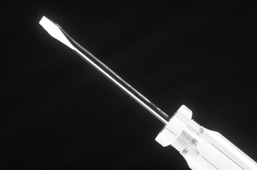
Screwdriver
1 four-way switch
2 three-way switches
Light fixture
Drywall patch kit

In a four-way switch configuration, three switches control a single fixture, whether it is a light, receptacle or other appliance. The configuration is called "four-way" because the middle switch in the circuit has four connecting terminals rather than the usual three found on most switches. Wiring a four-way circuit involves threading "traveler wires" carrying current among the switches, ending at the light fixture. This circuit uses an existing receptacle to tap into the branch circuit providing power.
Preparation and Running the Wiring
Step 1
Make the cuts in the wall and ceiling for the switches and fixture. Running the cable along the foot of the drywall is the easiest way to connect the switches. Above the last switch in the circuit -- switch 3 in this article -- make a small cut where the wall and ceiling meet to make threading the cable to the fixture easier.
Video of the Day
Step 2
Remove the baseboards along the path from the power source receptacle to each of the switches. Make a small cutout in the drywall beneath the switches and outlet for threading the cable.
Step 3
Run two-wire cable from the electrical source (outlet) to switch 1. The cable should fit in the 1/4-inch gap between the drywall and the floor. You may have to cut small grooves or drill holes to allow the cable to run around or through the studs. Leave 8 inches of wire exposed at each end.
Step 4
Run three-wire cable from switch 1 to switch 2 and two-wire cable from switch 2 to switch 3.
Step 5
Run two-wire cable from switch 3 to the light fixture using fish tape fed through the hole above switch 3 across the ceiling to the fixture hole. Attach the cable to the tape at the fixture and pull it back toward you. Drop the cable down to the switch hole.
Step 6
Install the boxes at the switches and the fixture. The fixture junction box is attached to the brace bar that is strung between two joists
Connecting the Wiring
Step 1
Connect the wiring at switch 1, attaching the black wire from the power source to the switch's labeled common terminal. Connect the red and black wires from switch 2 to the remaining terminals. Connect the remaining white wires and ground the switch to the switch box.
Step 2
Connect the wiring at switch 2 by connecting the two black wires to the left terminals of the switch and the two red wires to the right side. Connect the white wires together.
Step 3
Connect the wiring at switch 3 by connecting the fixture's black wire to the common terminal and the traveler wires to the remaining terminals. Connect the white wires together.
Step 4
Connect the fixture by attaching the black and white wires to their respective colors on the fixture. Hang the fixture according to the manufacturer's instructions. Attach the switches to their boxes, replace the baseboards and use the drywall repair kit to fix the hole above switch 3.
Tip
The middle switch -- switch 2 in this article -- must be the four-way switch. The other switches are three-ways.
Video of the Day