Things You'll Need
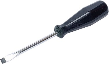
Screwdriver
Wire Pliers
Wire nuts
Black electrical tape

Six wire three-phase electric motors are dual voltage motors. How the wires are interconnected dictates the voltage being supplied to the motor. The supply voltage is either 240 volts alternating current (VAC) or 480 VAC. The motor will supply the same amount of power, but with a different load amperage. The higher the voltage, the lower the amperage.
480 VAC Wye Connection
Step 1
Remove all electrical power from the supply voltage leading to the motor. This will entail shutting off the main circuit breaker or pulling all three fuses for the three-phase power supply.
Video of the Day
Step 2
Remove the motor electrical connection box cover.
Step 3
Identify all wires within the motor connection box. The 480 VAC supply wires will be brown, orange and yellow. These wires are also identified as L1, L2 and L3 respectively. The wires coming from the motor windings are identified with numbers, T1, T2, T3, T4, T5 and T6.
Step 4
Join together T4, T5 and T6. Twist the bare copper ends with the wire pliers. Cover the three-wire connection with a wire nut.
Step 5
Join and twist the remaining wires in the following order. Connect L1 to T1. Secure L2 to T2. Attach L3 to T3. Cover all bare copper connections with a wire nut.
Step 6
Protect all connections from moisture by making three to four rounds of the black electrical tape over the wire nut connection. The tape must seal the bottom end of the wire nut to the wire insulation.
Step 7
Fold the wires carefully back inside the motor box. Replace the cover. Turn the electrical power on.
Step 8
Test rotation of motor. If motor is running backwards. Remove electrical power. Interchange L1 with L3, so L3 is now connected to T1 and L1 is attached to T3. The motor will run in the opposite direction.
240 VAC Delta Connection
Step 1
Remove all electrical power from circuit.
Step 2
Remove motor electrical connection box cover.
Step 3
Identify all power wires. The 240 VAC will have a black, red and blue wire for the power supply. Each identified as L1, L2 and L3 respectively. All motor wires will remain the same.
Step 4
Connect the wires in the following manner. Attach L1 to T1 and T6. Connect L2 to T2 and T4. Secure L3 to T3 and T5. Twist the three separate connections, one a time, with the wire pliers. Cover with three separate wire nuts. Protect against moisture with black electrical tape.
Step 5
Fold wires back inside motor electrical box. Replace cover. Turn on electrical power. Test rotation. Interchange any two main power leads, L1 and L3, if motor runs backwards.
Tip
Follow all local and National Electrical Code regulations when installing or servicing all electric equipment.
Video of the Day