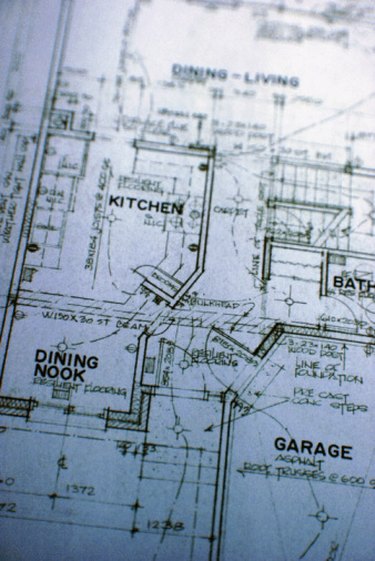
Professional drawers, draftsmen and architects, among many other technical professionals, use extension lines to present a clear-cut means for identifying key areas in blueprints, drafts and product manuals. With the correct use of extension lines, a complex image can become an accurate and usable product.
What Are Extension Lines?
Video of the Day
The term "extension line" is often used interchangeably with "dimension line"; however, they are two distinct tools when dealing with technical drawing. Dimension lines present certain measurements of and between items in a drawing. Extension lines, on the other hand, are seen simply as extensions of these items. Where items in blueprints can be busy and complex, an extension line is an easy way to interpret the basis of the item.
Video of the Day
Extension Lines and Dimension Lines
Extension lines usually connect dimension lines to different features on parts and images on the page. They are drawn perpendicularly when connecting dimension lines. For example, an extension line will reach beyond a complex object to connect with a dimension line that may give a specific height or distance. The extension line is an extension on the object.
Extension Line Specifics
When drawing an extension line, you should leave a 1/16-inch gap between the outline of an object and the beginning of an extension line. Extension lines will extend another 1/8-inch beyond the outermost dimension line.
Extension Line Breaks
Extension lines should never directly intersect with dimension lines or with object outlines on the page. Break the extension line on both sides of an object rather than cutting through an already existing line.